|
|

Accessory Mount (cont) |
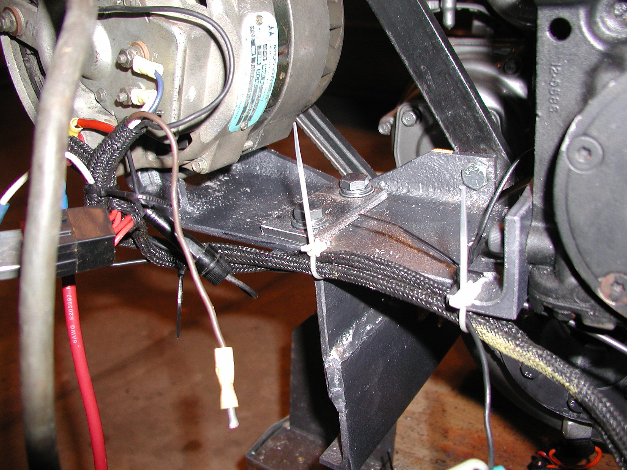
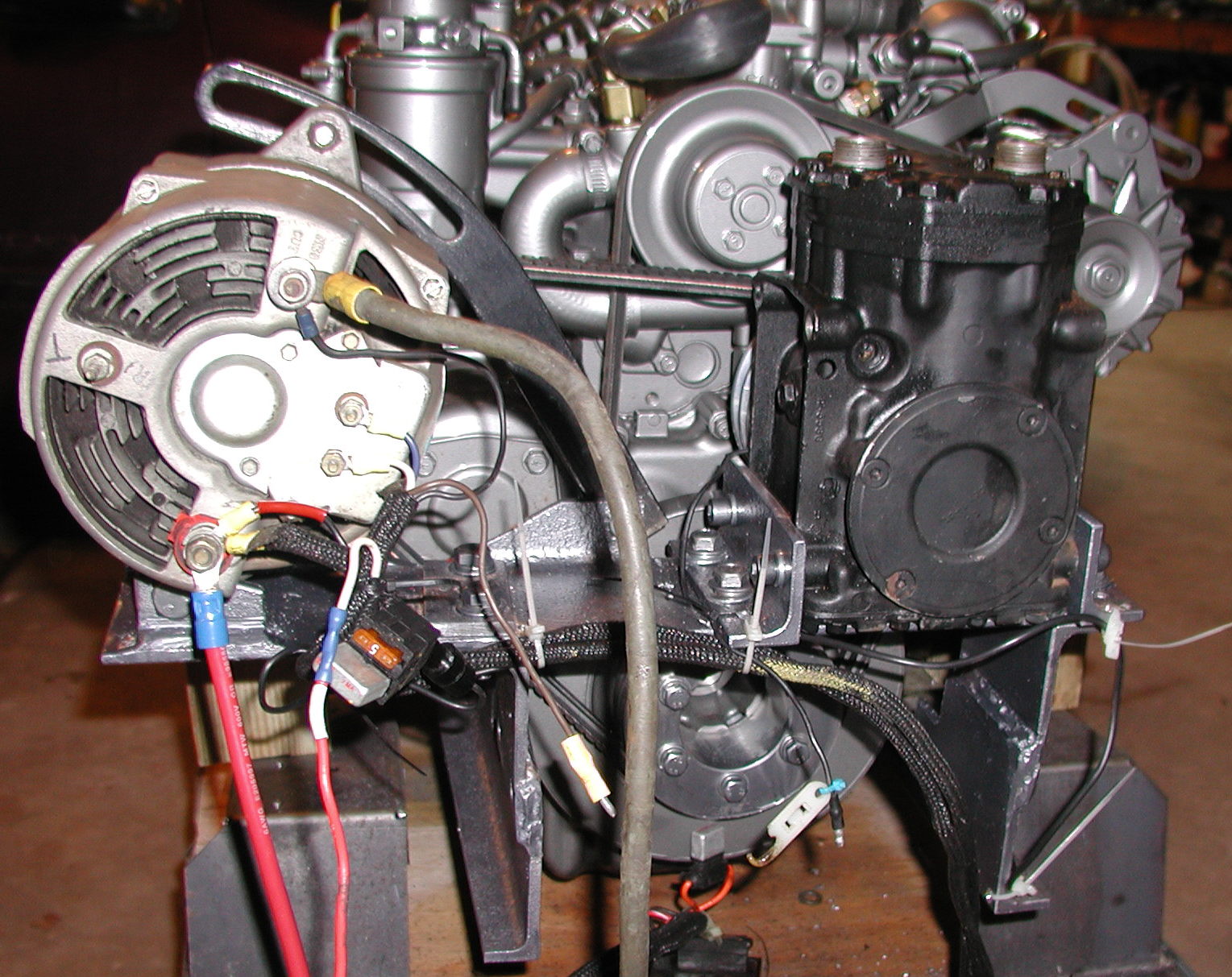
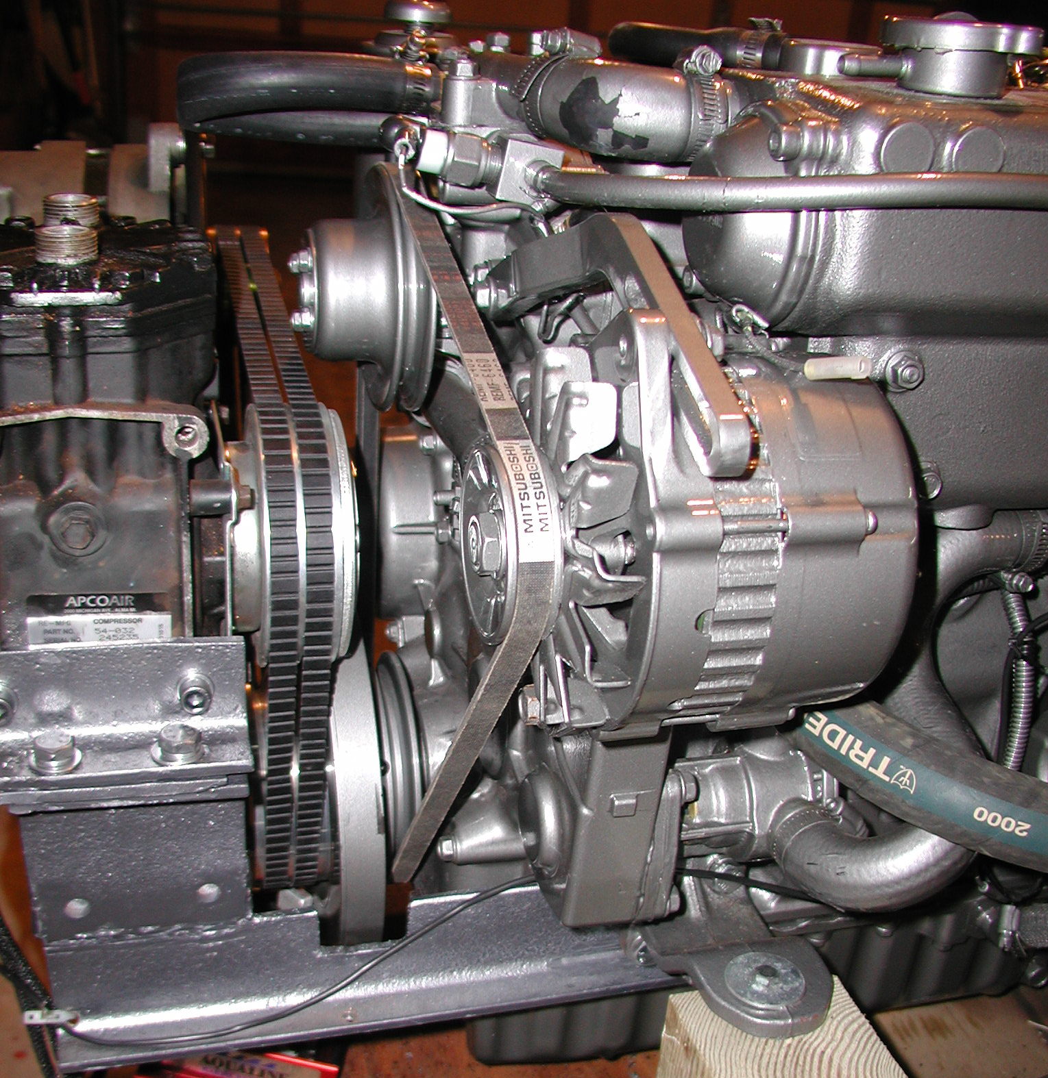
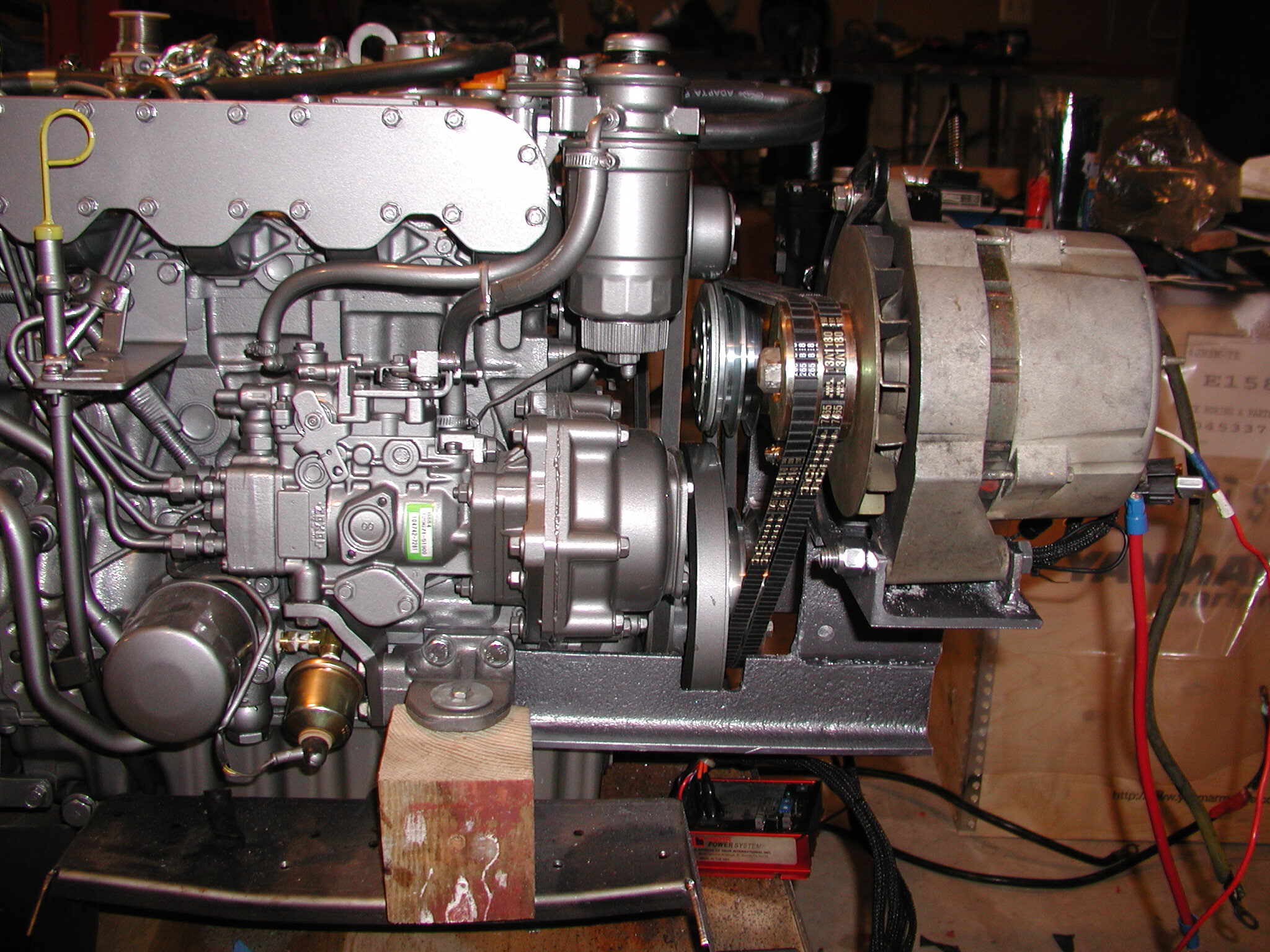
After cutting all the pieces, I positioned and clamped them to be sure about alignment and clearances before fastening the pieces together. I had to cut a small aluminum stud off the left side of engine beneath the fuel pump. This stud was unused and won't be missed. If the accessory pulley that I ordered had the pulley built with the sheaves a little farther from the engine, it would have been easier to position the refrigeration compressor. As it turned out, I had very little clearance below the water pump pulley. This would not have been an issue if the compressor could have been mounted about Ľ inch farther from the engine block. I arranged the accessories so that the same belt length used for the primary alternator and water pump will work on the accessories. It is important to consider clearances around the brackets and engine parts to allow replacement belts to be slipped into position. I planned on mounting the exhaust water-lift to the left side of the engine compartment, so I had position the accessory mounting platform to the right to insure room for the exhaust system. I used a mig-welder to attach the top mounting flare piece to the side brackets. I suppose it might be possible to drill and bolt the plate into position and avoid the weld. I first tried this approach, but found it difficult to keep the plates aligned while drilling. It may have worked if I removed them and used a drill-press to drill the holes. Instead, I ended up welding them in place. My welding skills aren't very good. Persistence compensated for my lack of skills. In addition to welding the top flange plates, I also welded the back mount for the alternator to the mounting plate. This could also have been done by bolting a plate into position, but a weld was easier. I bolted the top plate into position rather than welding it. I expect to remove the top plate to make the engine narrower while passing the engine through the companionway hatch. I also figured that a drilled plate would allow some minor repositioning. After finishing fabrication, I removed the whole assembly and painted it with a primer and close matching medium metallic gray color. In total, I spent about 32 hours making the mounting platform. An experienced metal fabricator with proper tools could probably do it in half this time. I would expect a shop to charge at least $500 to fabricate something like this and there is no guarantee that it will fit as well as what I made. After much research, I found that belts come in two basic designs, one is designed to take a shock load and the other is designed to wear well. The first type is thinner. It avoids damage when subjected to a shock load by slipping slightly. They usually come with ribs on the outside to provide better cooling. They tend to wear out quicker, but rarely snap. The other flavor has a thicker construction and slips less. These belts frequently have ribs on the inside. Since they have more surface area in contact with the sheave, they don't slip as easily. When subjected to a shock load, they may snap. My multi-stage regulator puts quite a load on the alternator when it switches to the fast charge setting. One of my battery banks has a pair of large AGM batteries. This type of battery accepts a recharge rate much faster than conventional wet-cell batteries. When the alternator kicks into high gear, it puts a chock load on the belts. I've had belts snap on me. When they break, they can be thrown off the pulley with considerable force. As mentioned earlier, I broke my throttle cable that way. Balmar recommends the Green Stripe belt by Gates. This is a low-slip belt that, in my opinion, is not suited to shock loads. They also recommend the Dayco Top-Cog V-belt. In my opinion, this will last longer and be more reliable. Since the same belt will work in for the primary alternator or the auxiliary alternator, I ordered two spares instead of three. |