|
|
Engine Bed |
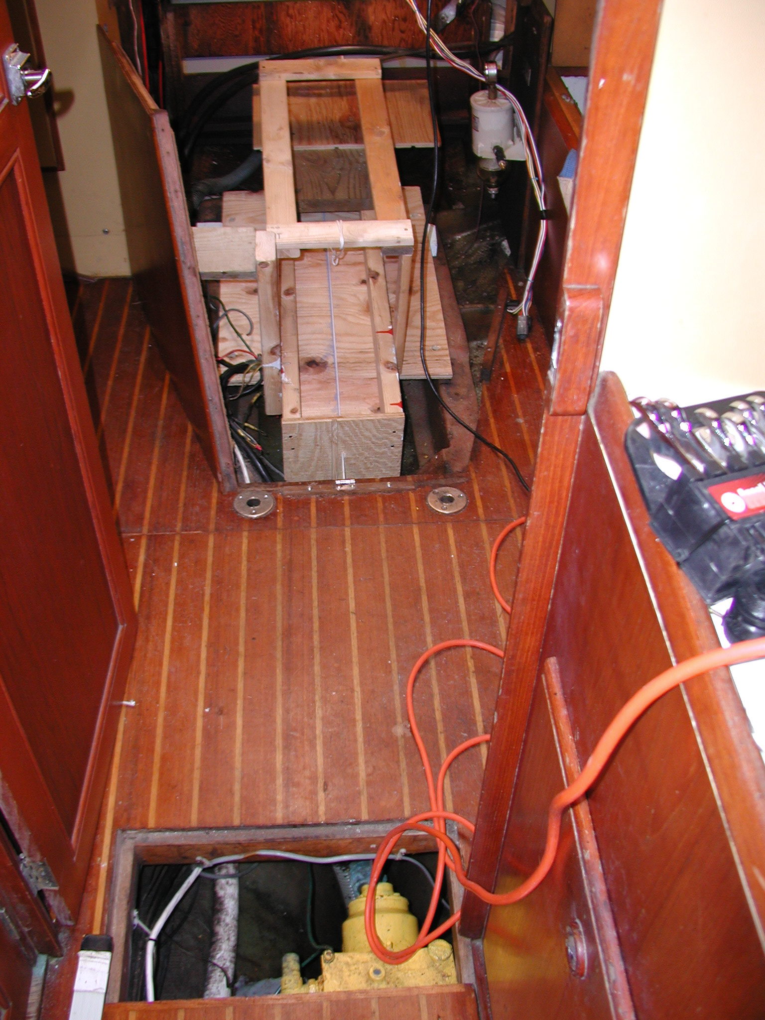
So how do you know if the engine is in straight? The photo below to the left shows the mock-up in position on top of the old pan. Engine mounts are not installed. Wooden shims were positioned under the mock-up to get it aligned with the v-drive shaft. The wood plate in the front of the engine simulates the shaft brake. The piece of string is shown running from the V-drive shaft hole through the mock-up and passes through a hole in the center of the simulated engine brake disk. If it passes through the disk hole cleanly, the mock-up is aligned. Once the mock-up was positioned correctly, I marked the engine pan at the appropriate height for the engine mounts and cut the pan out. |
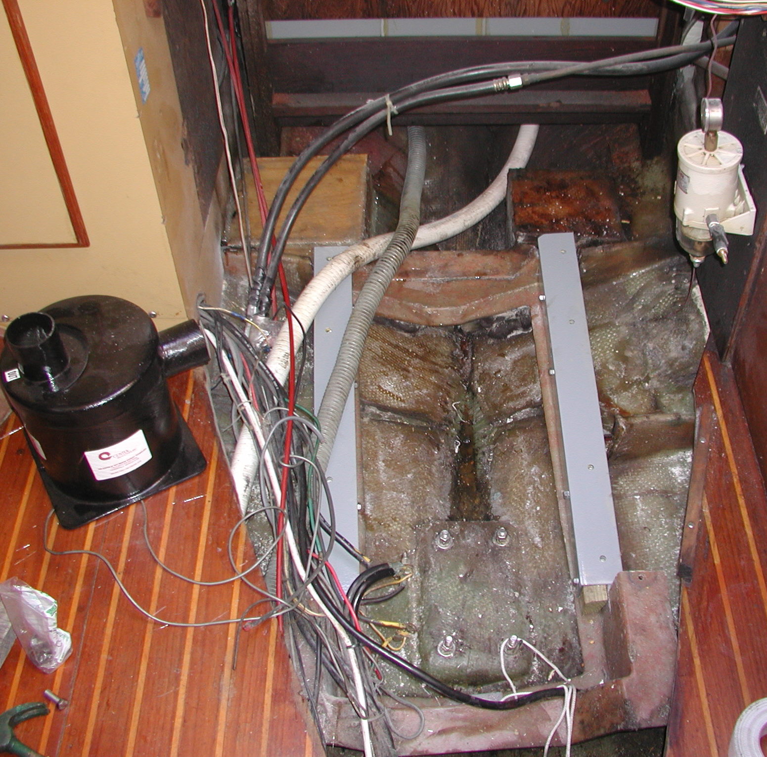
The photo above and center shows the engine mock-up in place sitting on the new bed and mounts. The top of the old bed was cut off and lowered about 3". A piece of pressure treated wood was glued inside the old pan to make it narrower. The shim is about 1.5” wide and 3” high, conveniently small enough to be cut from a PT 2x4. The shim is not square though. It had to be run through a table-saw to cut two sides to match the pitch of the pan. The steel bed is shown below the engine mounts. They were marked at the appropriate spots where the mounts will bolt to the pan. The block of wood on the left shows the position of the exhaust injection elbow. As shown, it just clears the inside of the engine cover after repositioning the engine back about 2 inches. I may have to cut out a small piece of the engine soundproofing on the inside of the cover. The photo above and to the left shows the new bed and the new muffler platform. The bed is made from 3" steel 'L' angle-iron bolted in place. It is pre-drilled for the engine mounts. Steel nuts are welded to the bottom of the bed to accept fasteners (7/16x20). The steel bed was painted with several coats of paint. The muffler shown on the left must mount on the opposite side of the old muffler, so I glassed in a new platform for it. The old muffler platform might be used for a starter battery box if there is sufficient room. In my case, the accessory platform interfered so I put the starter battery in the hanging locker. The area still needs to be cleaned up and painted. |
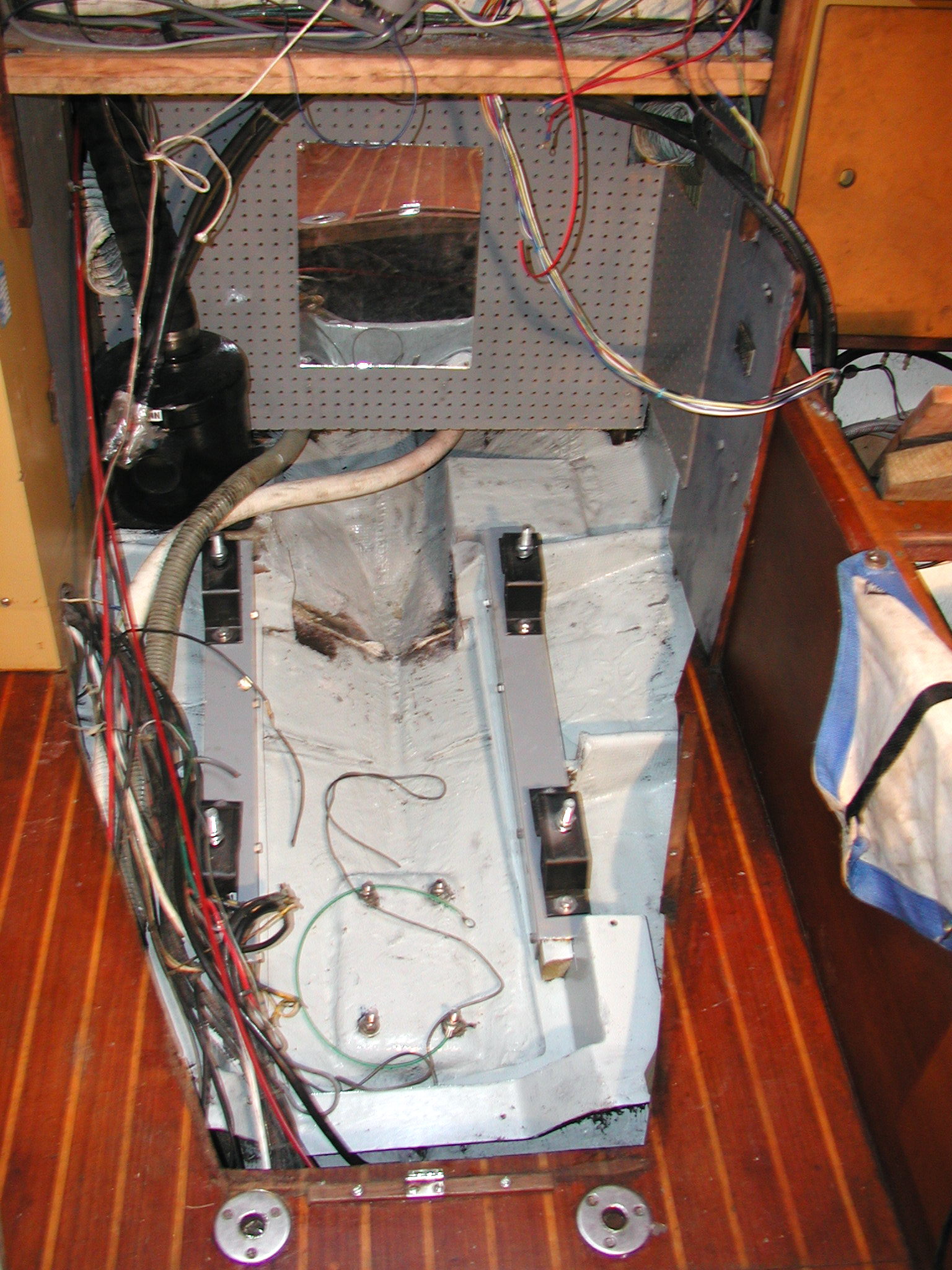
The photo to the left shows the completed engine room ready to accept the new engine. I had to cut the back of the old engine pan off because the PTO wouldn't clear it. This would have been a disaster if I hadn't caught it before the crane came to lift the engine in place. |