|
|
Engine Harness |
The instrument harness is another unimpressive Yanmar feature. To be fair, other than being wound up with a full roll of electrical tape, there is nothing really wrong with the harness. Their wiring diagram is another matter. The font is tiny. Even under a magnifier, it is difficult to read. They've used some kind of cryptic nomenclature consisting of a combination of letters and numbers on the diagram that is hard to decipher. Some signals change color codes as they run from panel-to-harness. They painted the engine after they wired it up; painting over the harness. It is almost impossible to trace the wires on the engine. The cable from the alternator to the starter appears to be too small. This shouldn't be a problem for me since I don't plan on using much power from the stock alternator. I'm not sure that the stock alternator is robust enough to stand up to use with a smart regulator. I would think that a Balmar unit of up to 80A could replace the stock alternator if someone else wanted to avoid the complexity of mounting a second alternator. I don't believe that a larger alternator could be installed in the stock position, though Balmar suggests that a single belt could drive up to a 110A unit. I think this optimistic. I split open the panel harness and removed the unused portion. I also cut it to length. I removed the ignition key subpanel and mounted it on the backside of the instrument cluster within reach behind the companionway ladder. This allows access to an ignition and shutoff switch during engine maintenance. I purchased a new pull switch switch for the ignition and toggle switches for start and shutoff. I mounted them on a new panel in the appropriate position next the right ankle of the helmsman. |
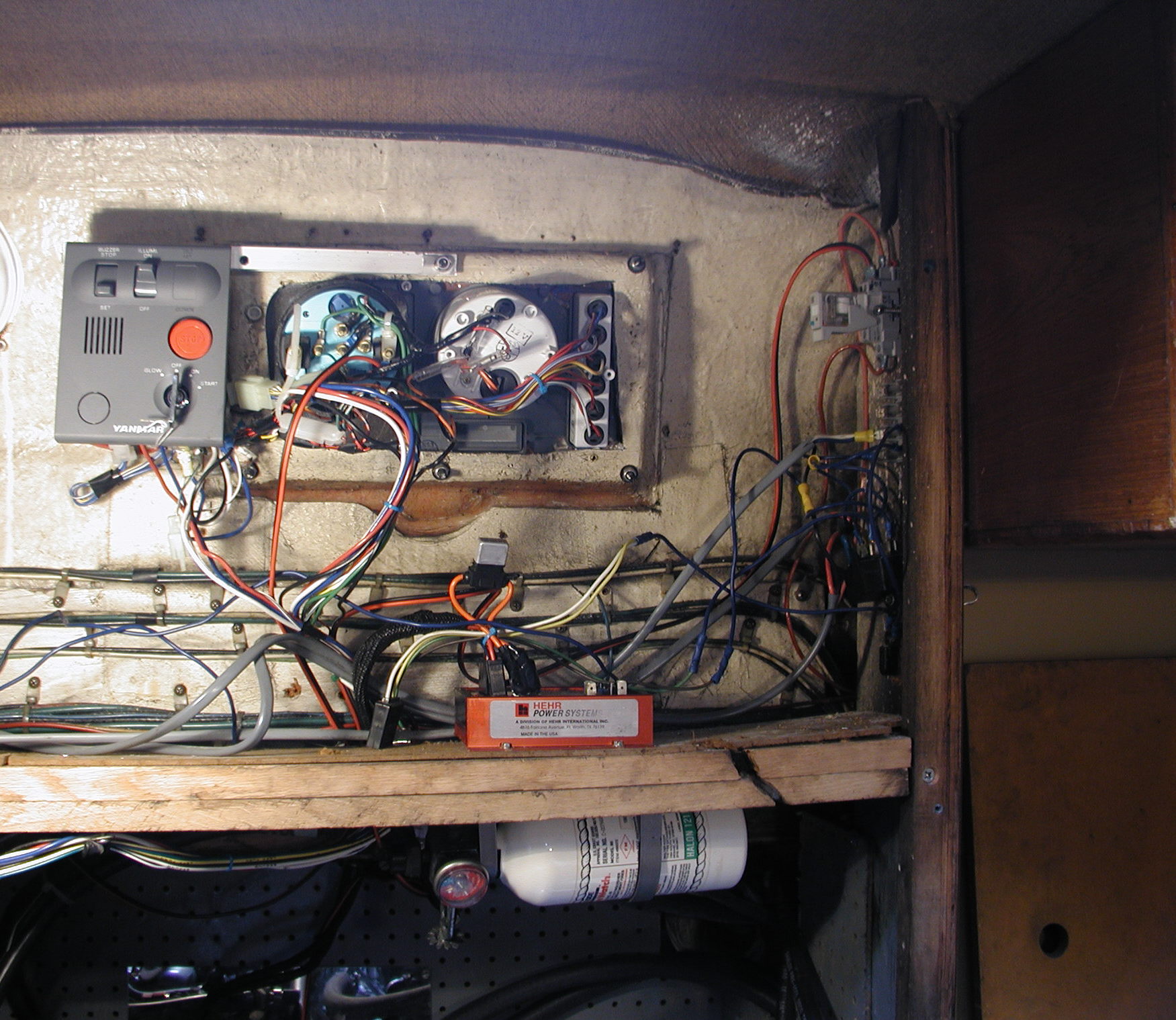
Photo to the left shows the instrument panel with service key panel mounted in position. Just below the insruments is the Aqualine regulator. An automatic fire extinguisher is just below the regulator. (click on photo for larger image) |