|
|
Engine Mock-Up |
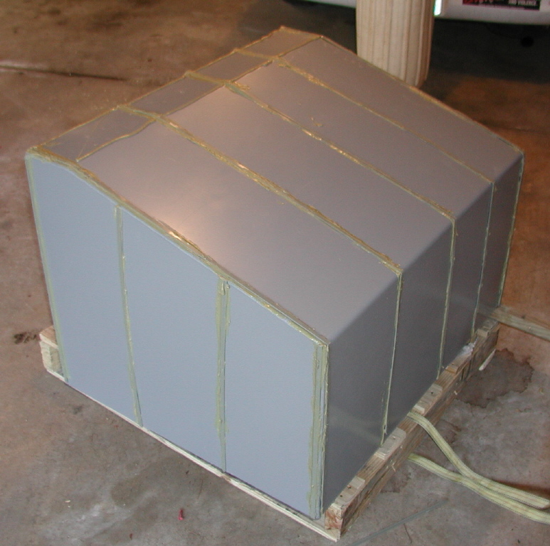
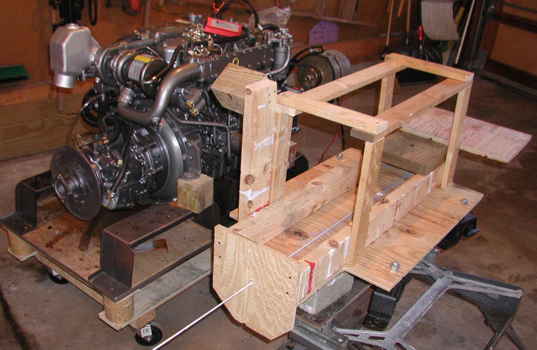
Research indicated that one key to a successful repower job is to build a good engine bed that properly aligns the engine to the shaft. The distributor sells steel mock-ups for this purpose, but they are available only in standard transmission configurations. I don't know if you can borrow or rent one, but this would be a sensible way to do business. In any case, since I was using a non-standard transmission, so I'd have to come up with my own mock-up. In order to make sure that I got the engine mounted right, I made my own mock-up of the engine. I reasoned that since the 424 used a V-drive in the drive train, engine alignment isn't as critical as a straight installation. Tolerances that I could achieve with a wooden mock-up would be good enough. There are a number of things to consider when positioning the engine. There is of course the alignment with the drive shaft. It is also important to insure that the exhaust system will have sufficient room and the engine room cover must fit back into position without having to cut holes in it for engine parts. No engineering drawings were available for the engine as configured with the SAE bell housing that I ordered. I had to take measurements off the engine after I received it. The engine mounts are all in alignment with the center axis of the drive shaft. I cut a piece of plywood that was large enough to cover the footprint of the engine. I drilled four holes in it at the appropriate position for each engine mount. Above that, I built a wooden box that approximates the size of the engine. There was a risk that the exhaust injection elbow would interfere with the engine cover, so I positioned a wooden block where the elbow would be. I attached a flat wooden plate where the transmission brake would be. This would be used to help position the engine. I added a flat plate at the front of the engine to simulate the position of the accessory mounting plate. This would allow me to verify that there would be sufficient clearance for the exhaust riser behind the engine. I drilled a hole in the center of the simulated brake disk and attached a screw-eye at the opposite end of the engine. This would allow me to draw a string through the engine mock-up down to the v-drive. If the mock-up is properly aligned, the string will pass through the center of the hole in the brake and then straight to the screw eye. The photo below shows the string through a hole in the simulated brake disk. My plan for aligning the engine is to first align the engine mock-up. Then make fine adjustments as necessary with the engine mount adjustments once the engine is in place. The engine mounts can be adjusted to the left/right approx ˝" using a slotted hole on one end of the base, and can be raised/lowered about the same amount using adjustment screws. They can't be moved forward/aft, so it will be important to get the distance between the forward and aft engine mounts correct. The distance between the engine and the V-drive is not critical. It took about four hours to fabricate the mock-up. (Click on photos for a larger picture.) |